Robotics-II-Circuit-Python
Circuit Python tutorials in Robotics II
View the Project on GitHub MrPrattASH/Robotics-II-Circuit-Python
Table of Contents
CircuitPython - FlySky FS-I6X Controller - FS-iA6B Reciever
This tutorial will serve as a reference for setting up the FlySky FS-i6X transmitter and FS-iA6B reciever with a metro M4 device. Theoretically, this should work for just about any RC controller that is capable of outputting a PWM signal. You can think of this page as more of a debug tutorial.
RC Intended output
- CH1 - Right joystick, Left/Right Control
- CH2 - Right joystick, Up/Down Control
- Ch3 - Left joystick, Left/Right Control
- CH4 - Left joystick, Up/Down Control
- CH5 - SWB, 2 way toggle switch
- CH6 - SWC, 3 way toggle switch
Eventually, we will drive the robot throttle with CH2, and steer with CH1. CH3/4 will likely not be used, and CH 5/6 will be used for various mechanisms attached to our robot.
Powering on switch states
- All toggle switches should be pushed UP, the OFF state
- Right joystick should auto centre, as it is spring loaded
- Left joystick should be pulled all the way down

Main Tutorial Credits & Documentation
Much of this tutorial is taken from several different sources. I include them here for future reference, as CircuitPython documentation is sparse online.
- Main Instruction manual for the FS-i6X controller
- An amazing tutorial on setting up the controller by Run Amok Combat Robotics. I have modified a decent portion of this tutorial to only provide relevant material here.
- this random thread from 2021 on a raspberryPi forum that provided the necessary PseudoCode for translating PWM into a useable signal. (April 01,2021 8:03am post)
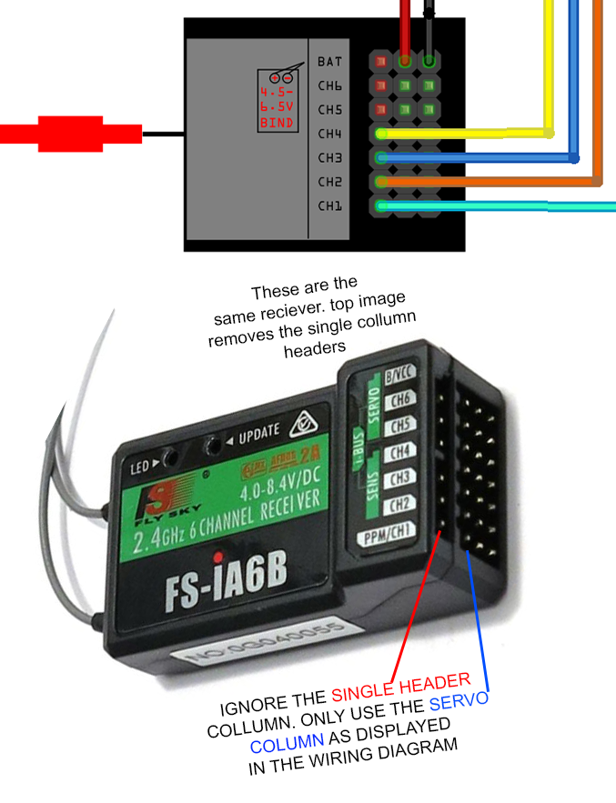
Wiring the Reciever
It is important to know that the receiver outputs a 5V signal. However, our CircuitPython board logic pins are only 3.3V, so we need to use a device called a LevelShifter, or Voltage changer, to shift 5V logic down to 3.3V logic. The level shifter we’re using in our class is bi-directional, meaning that it can convert both High > low voltage, and vice-versa. We need to wire an input voltage, 5V to the A or B side, an output voltage (3.3V) to the opposing side, and connect the GND to our M4. Then, we can easily convert A1 > B1 voltage, or B2 > A2 voltage, and so in. In our case, we’ll input 5V to the B side, and output 3.3V to the A side.
Isolating your Grounds
NOTE: You MUST isolate your ground circuit for your RC signal. This means that the ground wire cannot mix with other grounds in your circuit (ie, on your main GND rails). We do this to reduce elicrtical noise on the circuit, as other wires act as “antennas” and add random “noise” or spikes into our circuit. This helps keep our RC signal (relatively) clean so we can still send/recieve commands and signals.
Sample Code
In the folders above is a sample program for recieving RC signals.
- import rc.py into your lib folder on the M4
- run rc_example.py in code.py
- The rc.py defaults to these pins:
- Channel 1 - D7 - X axis joystick 1
- Channel 2 - D8 - Y axis joystick 1
- Channel 3 - D9 - x axis joystick 2
- Channel 4 - D10 - y axis joystick 2
- Channel 5 - D11 - SwB
- Channel 6 - D12 - SwC
Calibration of Joysticks “SubTrim”
Joysticks are unfortunately not all made the same. Some centre points are different than others, and this means that you’ll output a different PWM value depending on what controler you are using. Additionally, overtime joystick springs will relax and change their calibrated centre points. Likely, you’ll need to calibrate the joysticks overtime to gain more accurate readings. Upon initial setup, you’ll also need to calibrate the joysticks, and fiddle with the below settings. You may also notice that your wheels “twitch” at stop, this is also a good time to calibrate the joysticks “SubTrim”
*Note: If your robot will not use the left-joystick, there is no need to follow these steps for channels 3/4.
Setting up to Calibrate the Deadpoint
- Open rc_example.py and download this to your code.py file on the M4. run the code.
- We’ll calibrate channel 1 & channel 2. Repeat these steps for both (and modify your read channels/printed channels appropriately)
- On your controller, Centre the right joystick and look at the serial printout statements. Your goal is to have “1: 50” displaying, such as:
1: 50
1: 50
1: 50
1: 50
1: 50
...
If your controller is outputing 50 consistently , great! You don’t need to do the below steps. If not, you need to:
Centering the RC Deadpoint (Ch1, Ch2)
- press and hold ‘OK’ to enter the menu
- press ‘DOWN’ to select the ‘Functions Setup’. press ‘OK’
- press ‘DOWN’ to select ‘Subtrim’ press ‘OK’
- press ‘OK’ to select the correct channel (1 for X_joy1, 2 for Y_joy1). If your output is <50 hold ‘DOWN’ to move the centre subtrim to the left. Vice versa if your printed value is presenting positive.
- As you press ‘DOWN’ or ‘UP’, watch your serial output on your circuitPy board. You should notice it’s consistency improving over time. Once they’re far more consistently returning “50” than at initial calibration, you’re done.
- Repeat the steps for the 2nd analog joystick channel.
- Press and hold ‘CANCEL’ to save your settings.
Calibrating the Joystick Endpoints
Again, not all Joysticks are made the same. Some do not have as great of a range of motion as others do. You may have noticed that your motors may move faster in 1 direction than in a different direction. This is because your joysticks “range” is likely not exactly -1 & 1 respectively. This could be due to manufacturing defects in either the joystick instillation, the electronic components themselves, or the plastic housing. Whatever the reasoning, we can calibrate this as well.
- Use the same modified rc_example.py code from above to read the current outputs of the x/y axis on channel 1/2 on the right joystick.
- Push the joystick all the way left and look at the serial printout statements. Your goal is to have the highest, most consistent number displaying as possible. This is so that we have a reliable range output on our joystick axis’. For example, on my controller,
# most reliable, consistent readings
X min: 0-5
X max: 95-100
Y min: 0-5
Y max: 95-100
Likely, your controller is jumping between inconistent values at the endpoints of the controller, or even registering a value higher than mine. That’s okay, we don’t really care what the end number is, what we care about is the conistency/reliability of endpoint value readings. To calibrate:
- press and hold ‘OK’ to enter the menu
- press ‘DOWN’ to select the ‘Functions Setup’. press ‘OK’
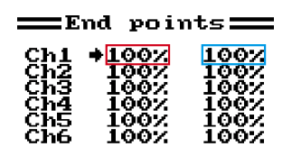
- press ‘DOWN’ to select ‘Endpoints’ press ‘OK’
- press ‘OK’ to select the correct channel. The left collumn (red) corresponds to the minimum joystick value, the right collumn (blue) corresponds to the maximum joystick value.
- Starting with Channel 1, hold your joystick all the way to the left. Look at what number you are displaying, and see if you are getting false highs outputting.
- As you’re holding the joystick, If you’re displaying inconsistent highs values, lower your channel endpoint slightly with the “Down” key on the transmitter.
- As you change the endpoint values, watch your serial output on the M4. You should notice the output’s consistency improving over time. Our goal is consistent readings, similar to when we calibrated the deadpoint “0” as above. The odd high spike is OK.
- Once the low endpoint is calibrated, move the joystick to the right all the way to the right. Watch the serial output.
- To change the top endpoint, you need to also use the joystick to select the correct collumn (convenient!). You’ll need to select the correct collumn, change the value slightly with Up/Down keys, then hold your joystick all the way right again & watch the serial output, repeat.
- Press OK to select ch2. Repeat steps 6-9 for Ch2.
- Press and hold ‘CANCEL’ to save your settings.
My controllers final endpoint values were:
Ch1 99% 99%
Ch2 99% 98%
And its most reliable, consistent readings:
X min: 4
X max: 95
Y min: 3
Y max: 96
Setting initial settings on the Transmitter
First, Put x4 AA into the transmitter & power it on.
Change AUX Switches
We need to change some default settings. Default AUX switches are VRA & VRB, x2 analog dials. We instead want to switch these over to SWC (3 way toggle switch) and SWB, a 2 way toggle switch. Since we’ll only use the right joystick for robot control, there is no need to have x4 analog sensors that we won’t use, so instead we’ll create 2 switches and 2 analog sensors.
- power on the transmitter
- press and hold ‘OK’ key to enter the menu screen
- highlight “System”, press ‘OK’ key
- tap ‘Down’ key until the “AUX Switches”. press ‘OK’ Key
- on this screeen, Up/Down turns on/off the current selection. Use ‘OK’ to cycle through options until you have the following settings:
- SwA: Off
- SwB: On
- SwC: On
- SwD: Off
- VrA: Off
- VrB: Off
- Ch: 6
- press and hold ‘CANCEL’ to save settings. (I know, holding cancel = save)
- press cancel again to return to the main menu
- press ‘DOWN’ key and select ‘Functions Setup’. press ‘OK’
- press ‘DOWN’ until ‘Aux. Channels’ is selected. press ‘OK’
- with Channel 5 selected, press ‘DOWN’ to select SwB. press ‘OK’
- with Channel 6 selected, press ‘DOWN’ to select SwC. press and hold ‘CANCEL’ to save settings
- press cancel x2 to exit the menu. AUX channels are now set.
Correct Failsafe
(credit to runamok source) We need to create a Failsafe for our transmitter. If for whatever reason our transmitter stops sending signals, our reciever will default to OFF, rather than continuing to fly/run away on us. The default failsafe ‘Off’ setting will lock the selected channel in the last setting it had before the transmitter signal was lost. That is not an acceptable response for a combat robot! Turning failsafe ‘On’ will return a receiver port to a pre-selected safe setting that will bring all motion on the robot to a stop – a correct failsafe response.
- Back at the ‘MENU’ Screen
- Tap the ‘Down’ key to highlight ‘System setup’ – tap ‘OK’ to select.
- Use the ‘Down’ key to scroll down the list to ‘RX Setup’ – tap ‘OK’ to select.
- Use the ‘Down’ key to scroll down the list to ‘Failsafe’ – tap ‘OK’ to select.
- Pull the left stick all the way down, and leave the other stick axis spring centered.
- Tap ‘OK’ to select channel 1, tap ‘Down’ to turn failsafe ‘On’, then ‘OK’ to return to channel selection. Tap ‘Down’ to the next channel and repeat for channels 2, 3 and 4. Your screen should look like:
- Channel 1: 0%
- Channel 2: 0%
- Channel 3: -99%
- Channel 4: 0%
- Channel 5: Off
- Channel 6: Off
- With all channels correctly set, press and hold ‘Cancel’ to exit and save the failsafe settings.
- Tap ‘Cancel’ three times to step back to the status display screen